
Please wait, I'm coming over...

//show loading message
Last Changed 12/27/2017 |
||
|
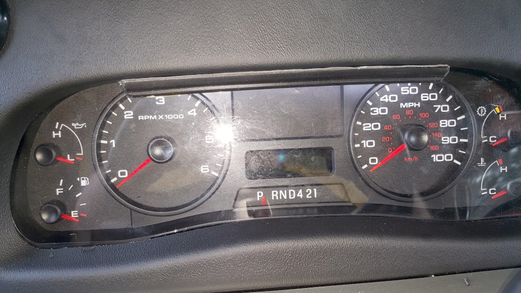
The position of the speedometer in the Ford gauge cluster is difficult to read
in most daylight conditions. And the type of instrument lighting used by
Ford in 2016 doesn't make is any better with the headlights on. |
||
Adding LEDS11/14/2016We decided to add a LED strip to the top of the instrument cluster. |
||
 |
First we removed the rearview monitor on the left side of the dash. We did this by sliding a thin piece of plastic to release the clips on the top of the monitor. |
|
 |
The frame for the monitor is held in place by two brackets which we removed. | |
click on images to enlarge |
||
 |
These are the two brackets that hold the rearview monitor frame. | |
 |
We then removed the radio from the right side of the dash. The bezel around the
radio snaps off. Then four small screws are removed to remove the radio. |
|
click on images to enlarge |
||
 |
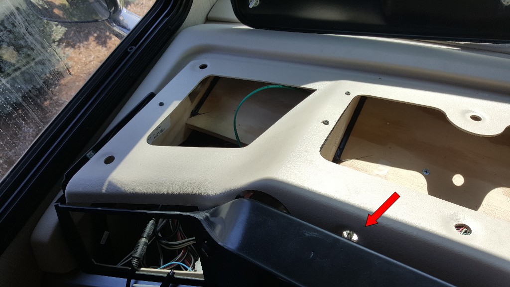
Facing the dash top, with the rearview monitor and radio removed, there are two nuts and washers to be removed from studs near the front of the dash top by reaching through the holes. Indicated by arrows. | |
 |
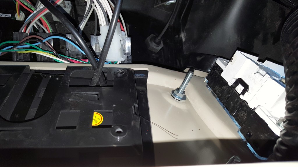
You need to loosen the nuts on the two studs near the back of the dash top. With the front nuts removed and the rear nuts loosened, you can raise the from of the dash top and reach in and remove the rear nuts and washers. It is very hard to remove the rear nuts through the monitor/radio holes. | |
click on images to enlarge |
||
When reinstalling the dash top, start the nuts on the rear studs with the front tilted up. Then drop the top and install the front nuts and tighten. |
||
 |
Note the studs on the dash top. The indicated studs in the center did not have nuts on them. | |
 |
We ran a piece of power cord over to the passenger side of the dash to connect to the DC
fuse block added. We used power cord as it have double insulation and is tougher. The power cord is orange. |
|
click on images to enlarge |
||
 |
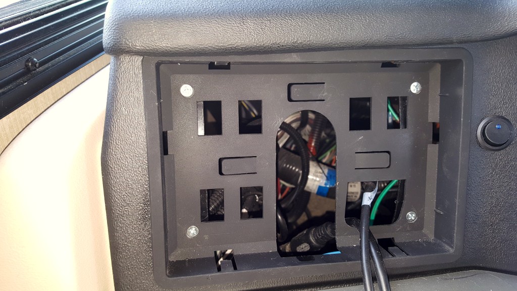
To get behind the black facia cover, there are 5 nuts on studs like indicated by the arrow to remove. This allows the facia to be tilted forward. | |
 |
The cream colored area between the black gauge assembly and the white switch assembly is where I drilled the hole for the switch. | |
click on images to enlarge |
||
 |
This is the switch I am using to turn the gauge LEDS on/off. | |
 |
I used LED self stick strip attached to a small PVC corner trim piece that was painted black. | |
click on images to enlarge |
||
 |
We used 3M red super-stick tape to attach the cornet trim to the gauge fascia. Unfortunately the flash lit the gauge assembly. |
|
 |
If you note the light from the LEDs on the top of the gauges. | |
Changing the LEDS12/27/2017The trim piece we used to attach the LEDS strip was thick enough to block the turn signal arrows on the instrument cluster. We decided to change the style f LED strip to one that was thinner.. |
||
 |
This LED strip has edge LEDS where the LEDS aim their light to the side compared to the
previous LED strip we used where the LEDS aimed up. We were able to just use the adhesive back of the Side Edge LED strip to attach it to the instrument cluster bezel. |
|
 |
We had to disassemble the dash as before to change the wiring to the opposite of the cluster. The new Side Edge LEDS are brighter and most importantly, do not block the turn signal arrows. |
|
Disclaimer: The information in this site is a collection of data we derived from the vendors and from our personal experiences. This information is meant as a learning guide for you to make your own decisions Best practices and code should always be followed. The recommendations we make are from our personal experiences and we do not receive any compensation for those recommendations. |